How to turn Piano toy into MIDI keyboard (using Arduino/Atmega)
Recently I've recovered a broken Casio SA-47 piano toy:

What a great opportunity to experiment I thought! I always wanted to make my own midi device and here was a chance. So I decided to make a midi keyboard.
Below is the video of the final result...
First thing during the keyboard autopsy I've got rid of all the intestines. The keyboard was implemented pretty much on a single chip so I took out the main board which left the toy with keyboard/keys part only and plenty of space to keep my PCB inside.
As you see from the picture keys are using simple On/Off circuit for each note so I was not expecting to make a velocity sensitive keyboard. In future posts I'll talk how volume/velocity and other expression can be added to this project so stay tuned... :)

Ok, we have got the keys now, we need something to read when keys are being pressed and released. After that, the event needs to be interpreted and passed to another device such as a PC or MIDI-enabled device that will hopefully do something useful such as play music or make some noise (that no one except yourself will enjoy... :)) We need a micro-controller. I've chosen to use Arduino board that uses ATMEGA based - programmable micro-controller. Arduino comes with IDE and number of examples. Arduino is one of many ATMEGA variants and there are plenty of compatible Arduino boards so feel free to use any other compatible device. The Arduino board usually comes in a kit with a breadboard, patch wires, resistors, sensors, LCD, LEDs, push buttons and other stuff that is cool to play with and experiment. I've got this one and found everything I needed so far:
https://www.sparkfun.com/products/11236
So coming back to Keyboard that we need to read. Keyboard has 32 notes/keys that can be pressed or released simultaneously. We are planning a polyphonic device so we need to make sure our controller is able to recognize more than one key pressed at the same time. Actually it will allow all 32 keys to be pressed at the same time which would likely never be required unless you got a monkey playing the piano... (I'll demonstrate it in my video :)). Casio Keys PCB (Pic1) uses scan matrix of 8 notes organized in 4 groups. 8*4=32 notes. In scan matrix terminology it is 8 columns and 4 rows. In order to read notes we need to scan 8 columns one by one and read 4.
If we use pure I/O of the Arduino we would require 12 I/O(s) which is more than we can afford. Instead we will use shift register controller that will use slightly less I/O(s) - 7.


To scan PCB we will use Parallel-out shift register technique. A very detailed description of Parallel-out shift register and other techniques available at below link:
http://www.openmusiclabs.com/learning/digital/input-matrix-scanning/shift-out-mux/
In short Parallel-out is one of the effective scanning techniques available in terms of number of Digital I/O used, scan time and response time.
Parallel-out shift register was implemented using 74HN595 shift-register chip that was available in the Arduino kit that I bought. Here is a good tutorial on 74HN595 if you would like to understand the principles behind the work of the chip:
http://www.arduino.cc/en/Tutorial/ShiftOut
I've ended up with relatively simple schematics below:

As you see connector from Controller schematics J1 has 8 columns and 4 rows that are matching to the existing keyboard schematic.
If you would like to try it first below is a breadboard diagram.

First controller prototype was made on the Arduino breadboard. After that controller was transferred to a Freetronics Protoshield that was meant specifically for Arduino board. The good thing about the size and the pin outs are perfectly matching Arduino and not only project will look professional but all components will fit nicely together. :)


After assembling all main components below is the working components necessary to implement a MIDI keyboard.

Below is the source code for Midi keyboard. You will need to open code in Arduino IDE and upload it:
Please note you might need to re-arrange the mapping of the notes to MIDI in keyToMidiMap based on the order you wire Keyboard Rows to Row pins.
The view after placing keyboard PCB back to casing:

The bottom of the keyboard casing with Arduino shield fixed with silicone glue and holes made for connectors. As well you see the container that will hold different MIDI enabled sound modules.

Casing closed and final look without sound module.

Below is Yamaha QY-100 sound module fits nicely.

Hope you enjoyed it!... :) Happy tinkering!
Continue to the second part of the project here where we add Velocity and After touch to the keyboard. And here is the third part on how to enable USB connectivity to your PC.

Pic1: Keyboard
What a great opportunity to experiment I thought! I always wanted to make my own midi device and here was a chance. So I decided to make a midi keyboard.
Below is the video of the final result...
For those interested there is a second part of the project here where we add Velocity and After touch to the keyboard.
>>> UPDATE: Thanks for your interest! MIDI Kit available here! <<<
First thing during the keyboard autopsy I've got rid of all the intestines. The keyboard was implemented pretty much on a single chip so I took out the main board which left the toy with keyboard/keys part only and plenty of space to keep my PCB inside.
As you see from the picture keys are using simple On/Off circuit for each note so I was not expecting to make a velocity sensitive keyboard. In future posts I'll talk how volume/velocity and other expression can be added to this project so stay tuned... :)

Pic 2: Keys PCB
Ok, we have got the keys now, we need something to read when keys are being pressed and released. After that, the event needs to be interpreted and passed to another device such as a PC or MIDI-enabled device that will hopefully do something useful such as play music or make some noise (that no one except yourself will enjoy... :)) We need a micro-controller. I've chosen to use Arduino board that uses ATMEGA based - programmable micro-controller. Arduino comes with IDE and number of examples. Arduino is one of many ATMEGA variants and there are plenty of compatible Arduino boards so feel free to use any other compatible device. The Arduino board usually comes in a kit with a breadboard, patch wires, resistors, sensors, LCD, LEDs, push buttons and other stuff that is cool to play with and experiment. I've got this one and found everything I needed so far:
https://www.sparkfun.com/products/11236
So coming back to Keyboard that we need to read. Keyboard has 32 notes/keys that can be pressed or released simultaneously. We are planning a polyphonic device so we need to make sure our controller is able to recognize more than one key pressed at the same time. Actually it will allow all 32 keys to be pressed at the same time which would likely never be required unless you got a monkey playing the piano... (I'll demonstrate it in my video :)). Casio Keys PCB (Pic1) uses scan matrix of 8 notes organized in 4 groups. 8*4=32 notes. In scan matrix terminology it is 8 columns and 4 rows. In order to read notes we need to scan 8 columns one by one and read 4.
If we use pure I/O of the Arduino we would require 12 I/O(s) which is more than we can afford. Instead we will use shift register controller that will use slightly less I/O(s) - 7.

Pic 3. Keys scan matrix 8 Columns (Red) and 4 Rows (Yellow)

Pic 4. Keys PCB schematic. Columns (red) and Rows (yellow).
To scan PCB we will use Parallel-out shift register technique. A very detailed description of Parallel-out shift register and other techniques available at below link:
http://www.openmusiclabs.com/learning/digital/input-matrix-scanning/shift-out-mux/
In short Parallel-out is one of the effective scanning techniques available in terms of number of Digital I/O used, scan time and response time.
Parallel-out shift register was implemented using 74HN595 shift-register chip that was available in the Arduino kit that I bought. Here is a good tutorial on 74HN595 if you would like to understand the principles behind the work of the chip:
http://www.arduino.cc/en/Tutorial/ShiftOut
I've ended up with relatively simple schematics below:

Pic 5: Controller schematics
As you see connector from Controller schematics J1 has 8 columns and 4 rows that are matching to the existing keyboard schematic.
Assembly List
| Label | Part Type | Properties |
|---|---|---|
| Arduino1 | Arduino | processor ATmega; variant Arduino UNO R3 |
| J1 | Generic female header - 12 pins | package THT; hole size 1.0mm,0.508mm; row single; form ♀ (female); pins 12; pin spacing 0.1in (2.54mm) |
| MIDI OUT | DIN-5 jack (MIDI) | package THT; form jack (female); pins 5 |
| R1 | 10k Ω Resistor | package THT; tolerance ±5%; bands 4; resistance 10kΩ; pin spacing 400 mil |
| R2 | 10k Ω Resistor | package THT; tolerance ±5%; bands 4; resistance 10kΩ; pin spacing 400 mil |
| R3 | 10k Ω Resistor | package THT; tolerance ±5%; bands 4; resistance 10kΩ; pin spacing 400 mil |
| R4 | 10k Ω Resistor | package THT; tolerance ±5%; bands 4; resistance 10kΩ; pin spacing 400 mil |
| R5 | 220 Ω Resistor | package THT; tolerance ±5%; bands 4; resistance 220Ω; pin spacing 400 mil |
| U2 | 74HC595 | package DIP16 [THT]; type 74HC595 |
If you would like to try it first below is a breadboard diagram.
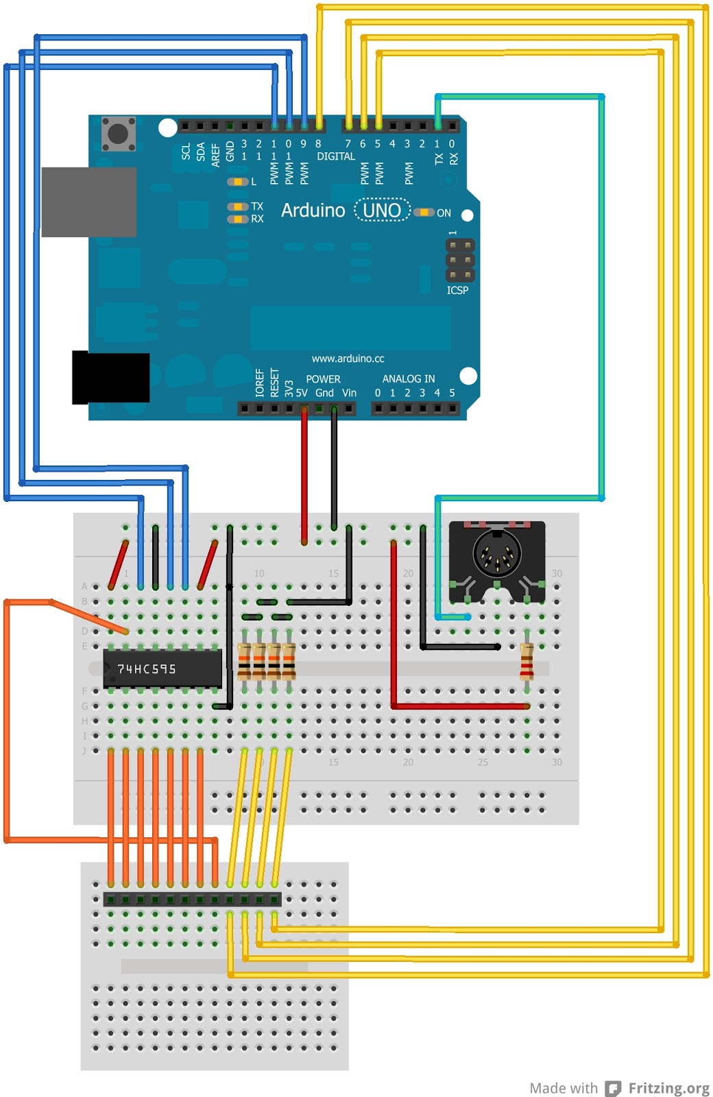
Pic 6: Controller prototype on a bread board
First controller prototype was made on the Arduino breadboard. After that controller was transferred to a Freetronics Protoshield that was meant specifically for Arduino board. The good thing about the size and the pin outs are perfectly matching Arduino and not only project will look professional but all components will fit nicely together. :)


After assembling all main components below is the working components necessary to implement a MIDI keyboard.

Pic 9: Keyboard logic components sufficient for operation.
Below is the source code for Midi keyboard. You will need to open code in Arduino IDE and upload it:
Please note you might need to re-arrange the mapping of the notes to MIDI in keyToMidiMap based on the order you wire Keyboard Rows to Row pins.

The bottom of the keyboard casing with Arduino shield fixed with silicone glue and holes made for connectors. As well you see the container that will hold different MIDI enabled sound modules.

Casing closed and final look without sound module.

Below is Yamaha QY-100 sound module fits nicely.

Hope you enjoyed it!... :) Happy tinkering!
Continue to the second part of the project here where we add Velocity and After touch to the keyboard. And here is the third part on how to enable USB connectivity to your PC.